
Proudly Hand-Built in America!
Pit Stop Performance instructions for Z1, KZ900, KZ1000 Top End Assembly
Last updated 2/14/2010
Gap the piston rings.
If you purchased your pistons from Pit Stop Performance and had your cylinder bored by Pit Stop Performance, you are in luck.
Your piston rings have already been gapped and you may skip this step.
If not, proceed with the following:
- Calculate your ideal ring gap. The ideal ring gap for an air cooled motor should be .004” for every inch of bore. So, for a 1075cc Z1 motor the piston is 72mm or approximately 2.834”. To calculate the ideal ring gap, multiply .004” by 2.8, the result is .011”.
- Place the top compression ring in the cylinder.
- Push the ring down by inverting a piston and using the top of it to push the ring down evenly until the top of the oil ring groove in the piston is even with the top of the sleeve .
- Remove the piston and measure the gap between the two ends of the ring with a feeler gauge. If your measured gap is less then your calculated ideal ring gap, you will have to remove material from one end of the ring to obtain the ideal ring gap.
- Remove the ring from the cylinder. Very carefully remove some material from one end of the ring using a fine file, a wet stone or a diamond stone. Be very careful to keep the end of the ring square. Remove only a small amount of material at a time.
- Repeat steps 2, 3, 4 and 5 until the ideal ring gap is achieved.
- Deburr the edges of the ring where the material was removed.
- Repeat steps 2 through 7 for the second compression ring.
- Place these gapped rings with the piston for the bore just sized.
- Repeat the ring gapping procedure for the other three sets of rings for each cylinder bore.
Install the piston rings on the piston.
 The piston and rings are matched to the bore.
If you had your cylinder bored by Pit Stop Performance, you are in luck, each piston is identified to it’s bore with a small number etched inside the skirt of the piston on the exhaust side, at the bottom.
The pistons are numbered from left to right sitting on the bike.
Start with the oil expansion ring, install it in the bottom groove and place the gap toward the back of the piston. Be sure that the ends of the expansion ring are butted up against each other and not overlapped. Hold the piston so that you are looking at the gap in the expansion ring. Install the top scraper ring next. Place the gap of the top scraper ring approximately one inch from the gap in the expansion ring. Install the bottom scraper ring next. Place the gap of the bottom scraper ring approximately one inch from the gap in the expansion ring on the opposite side from the gap in the top scraper ring.
Install the second compression ring and finally, install the top compression ring.
Note that the compression rings are directional. Both compression rings will have a letter or some type of symbol on the ring (usually an “N”). This letter or symbol identifies the top of the ring. Be sure to install them correctly.
If the motor is going to be assembled and started immediately, the rings should be lubricated with WD40. Spray the rings generously and then work them around the piston. If the motor will sit for a long time prior to being started, then the rings should be lubricated with a very light oil (sewing machine oil)
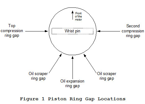
Arrange the gaps in the piston rings to match Figure 1 Piston Ring Gap Locations.
Note that the front of the piston can be identified by the smaller size valve reliefs, the exhaust valves are smaller than the intakes and so are the valve reliefs.
Install ring compressors.
Install hose clamps on the rings to act as ring compressors. Snug the hose clamps at this time. Leave them loose enough to allow movement up and down. Do not allow the hose clamps to extend low enough to interfere with wrist pin installation.
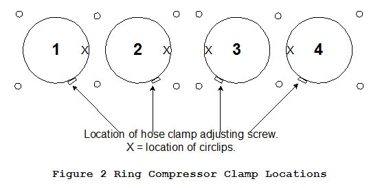
Position the adjusting screw of the hose clamps to match Figure 2 Ring Compressor Clamp Locations.
Install Circlips (if in use).
If your pistons are not MTC, then you are likely using circlips. Install one circlip in each piston on the inside, the locations are identified by an X on Figure 2 Ring Compressor Clamp Locations. Piston 1 and 2, install the right circlip, piston 3 and 4 install the left circlip.
Lubricate the wrist pin bore with 30 weight oil and install the wrist pin. Slide the pin in and out and rotate to spread the oil around and verify free movement.
Prep the motor for piston installation.
There are a number of small parts required:
(1) rubber cam chain guide roller
(1) steel guide roller shaft (for the rubber guide roller)
(2) rubber guide roller blocks [.299” x .357” x
.500”] (for each side of the steel shaft)
(2) steel dowel pins [.549”D x .480”L].
Install or verify already installed, two steel dowels [.549”D x .480”L] on the front left and front right cylinder studs. Verify the dowels are installed to a depth of approximately .240” in the case. If necessary the dowel may be seated in the case by placing a 7/16” or 10mm open end wrench on top of the dowel and tapping lightly with a small hammer.
Install the rubber cam chain guide roller with the steel guide roller shaft. Lubricate the shaft before assembling the two.
Install two rubber guide roller blocks [.299” x .357” x .500”] on each end of the steel guide roller shaft.
Install the cylinder base gasket. It only goes one way, be certain it is correct.
Install the pistons.
Pull the cam chain up and rotate the motor until connecting rods 2 and 3 are all the way up.
Lubricate the connecting rod wrist pin bores with 30 weight oil.
Install piston 2 from the left side of the motor as follows. Push the wrist pin out until it is flush with the inside of the piston bore. Hold the connecting rod up with your left hand and slide the piston on the connecting rod with your right. Line the wrist pin up with the connecting rod bore by sighting through the wrist pin hole. Push the wrist pin through the connecting rod until it has sufficient room for the wrist pin buttons to be installed or (until the circlip groove is visible). Lubricate the wrist pin buttons and install one on each side of the wrist pin, or (install the outside circlip). Push the ring compressor (hose clamp) down until the top of it is even with the upper edge of the top compression ring. Tighten the clamp until the compression ring gap closes.
Position the clamp adjusting screw as shown in Figure 2 Ring Compressor Clamp Locations.
Install piston 3 from the right side of the motor using all of the same procedures.
Pull the cam chain up and rotate the motor until connecting rods 1 and 4 are all the way up.
Lubricate the connecting rod wrist pin bores with 30 weight oil.
Install piston 1 from the left and piston 4 from the right using all of the same procedures as before.
Building piston installation blocks.
 Next we will build a couple of simple tools to aid in the assembly of the cylinder onto the pistons.
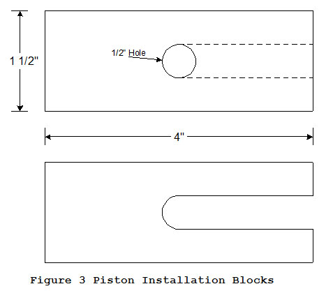
Start with two pieces of three quarter inch thick wood, cut to one and one-half inches wide by four inches long. Drill a ½” diameter hole two and one half inches from one end. Cut on the dotted lines shown in the top figure of Figure 3 Piston Installation Blocks and remove the material, cutting from the long end of the block.
You are left with two Piston Installation Blocks which should look like the bottom figure in Figure 3 Piston Installation Blocks with the slot offset to one side by a half inch.
Install the cylinder.
Pull the cam chain up and rotate the motor until pistons two and three are an inch or more above the base gasket surface.
Place a Piston Installation Block under the number two piston from the front of the motor and the other one under the number three piston. Rotate the motor to bring pistons two and three down and into contact with the Piston Installation Blocks
Lubricate the cylinder bores with WD40 or a light sewing machine oil. Gently lower the cylinder onto the studs until it comes into contact with the tops of the number two and three pistons.
Take a few minutes to make sure that pistons two and three are lined up exactly with their cylinder and that the pistons are sitting parallel to the bore. Keep an even downward pressure on the cylinder during installation to prevent the rings from coming back out of the cylinder once they have started in. The hose clamps will move down out of the way as the cylinder advances onto the pistons. The cylinder is advanced by alternately tapping on each end using a rubber mallet. Do not allow one side to advance more than a quarter of an inch ahead of the other side.
Be sure to look closely as the cylinder is advanced onto the pistons to be certain the rings are going into the bore and the pistons are remaining straight.
Once all of the rings for pistons two and three are inside their bores, the hose clamps may be removed.
Remove the Piston Installation Blocks from pistons two and three.
Continue to advance the cylinder following all of the same procedures until the rings for pistons number one and four are in their bores, then remove the hose clamps.
The cylinder can be pushed down by hand. The final push onto the dowel pins may require the rubber mallet.
Once the cylinder is installed, pull the cam chain up and make sure the motor will rotate easily. Turn the motor through several times to verify free rotation.
Prep the motor for head installation.
There are a number of small parts required:
(2) front and rear cam chain idler assembly
(2) steel guide roller shaft (for the cam chain idler
assemblies)
(4) small rubber guide roller blocks [.191” x .302” x .420”]
(for each end of the steel guide roller shafts)
(12) 10mm head nuts
(12) copper or steel 10mm washers
(2) 6mm shouldered bolts.
(1) cam chain tensioner assembly (for the rear cam chain idler
assembly guide roller shaft)
(2) steel dowel pins [.393”D x .545”L] (may be in the
cylinder).
Wipe the top of the cylinder and the bottom of the head with alcohol, laquer thinner or acetone to remove any dirt or oily film.
Apply a thin coat of Gasgacinch gasket sealer to the top of the cylinder, the bottom of the head and both sides of the head gasket. Hang the head gasket up to dry.
Gasgacinch is a contact adhesive, the surfaces need to be allowed to
Dry to a tacky state for about 30 minutes.
After the Gasgacinch has dried to “tacky” on the head gasket, smear on
a ring of Yamabond 4 (or Threebond liquid gasket 1194) around both the top and bottom of the outside four stud holes on the head gasket. Yamabond 4 (and Threebond liquid gasket 1194) is a semi drying liquid gasket material. I put about a 1/4″ diameter ball of it at the hole and then smear it around evenly with my finger. Hang the gasket back up until needed.
Install or verify installed one steel dowel pin in the outermost right and left hole in the cylinder.
Lubricate the inside of the front cam chain idler assembly and install the steel guide roller shaft. Place a small rubber guide roller block on the cutout on each side of the roller shaft and install the entire assembly in the front idler assembly slot.
Lubricate the inside of the rear cam chain idler assembly, install the cam chain roller tensioner assembly and secure with the steel guide roller shaft. Place a small rubber guide roller block on the cutout on each side of the roller shaft and install the entire assembly in the rear idler assembly slot. Be certain that the rubber roller (or the sprocket in the case of a Liska part) faces the front of the motor.
If you are using a two piece head gasket with a center rubber o’ring, then install those parts at this time.
If you are using a one piece head gasket, fill the groove where the
rectangular o’ring goes around the chain galley with Permatex
High-Temp RTV Silicone. Fill the groove completely. Allow the RTV
to stick up above the cylinder surface about 1/16″.
Then install the head gasket. The head gasket only goes on one way, be certain it is correct.
Install the head.
 Align the head on the studs, and slowly lower it into place. Push down on the head to force it over the two outside dowel pins. Do not push down on the horizontal fins (they snap off very easily).
Place a head nut washer on each stud.
Lubricate the threads of the head nuts with 30 weight oil and install the nuts using a 14mm socket. Advance the nuts by hand until they contact the washers.
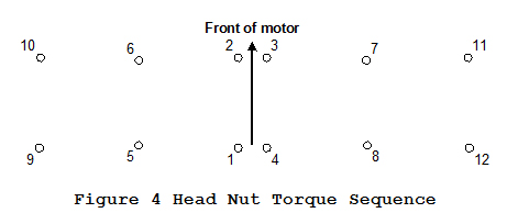
Torque head nuts following the pattern on Figure 4 head Nut Torque Sequence. If your motor is equipped with APE heavy duty cylinder studs and APE heavy duty head nuts, your final torque will be 35 foot pounds. The torque should progress in three stages of 12, 24 and finally 35 foot pounds. If your motor has stock cylinder studs, your final torque will be 18 foot pounds. The torque should progress in three stages of 6, 12 and finally 18 foot pounds.
Once the head nuts are secure, lubricate the two 6mm shouldered bolts and install in the two outside dowel pin holes. Torque to 70 inch pounds, or snug if you have no inch pound torque wrench.
Pull the cam chain up and rotate the motor several complete revolutions to verify smooth movement and no interference.
Install the camshafts (ROLLER CHAIN ONLY).
This method only applies to motors with roller chain.
If the camshafts and/or cam followers are new, there is an extra step that MUST be performed. If the camshafts and cam followers are not new, this step is optional. Coat the camshaft lobes and the top of the cam followers (or shims) with the supplied lubricant. The lubricant is normally a form of molybdenum disulfide. It is a dark grey to black thick grease that will adhere very well to the camshaft lobes and cam followers. Coat the lobes and cam followers completely.
If the camshafts are new, there is one other item that is extremely important to break in. The motor should be filled with one of the following oils, Shell Rotella T, Chevron Delo 400 or Mobil DELVAC. These oils are listed as diesel oils. They contain an important additive that is missing from most automotive oils. Do not use synthetic oil for break in under any circumstance.
First, If using a stock cam chain tensioner, remove the cam chain tensioner. Loosen the jam nut and the bolt, push the tensioner plunger inside the assembly as far as it will go. Tighten the bolt to hold the plunger in place. Leave the jam nut loose at this time. Reinstall the cam chain tensioner using a new gasket. If using an APE manual cam chain tensioner, loosen the jam nut and back the tensioner adjustin bolt all the way out.
Next, remove the tach drive gear. This is to prevent damage to the gear or the exhaust camshaft during installation.
In order to verify that the cam chain is properly engaged with the sprocket on the crankshaft, it is necessary to have the bike sitting straight up. If it is on the center stand, then you are OK. If not, you will have to manually tilt the bike to straight up then hold the cam chain with two hands. Pull it up tight against the crankshaft. Allow a little slack in the cahin sufficient to drop below the crackshaft sprocket. Then hold the chain in the middle of the gap side to side and pull it up snug against the crankshaft. Verify the chain is on the crankshaft sprocket by pulling alternately with your right and left hands. The crankshaft should rotate with your pull. Do not allow the cam chain to go slack at any time during camshaft installation.
While holding the cam chain up, rotate the motor until pistons 1 and 4 are at top dead center (TDC). This is determined by looking at the ignition advancer. It will have markings that indicate 1-4 T and F. the T stands for TDC and the F for fire (where the ignition timing fires). Be certain that the cam chain is solidly engage to the sprocket on the crankshaft.
Verify that eight babbet cam bearings are in place in the head.
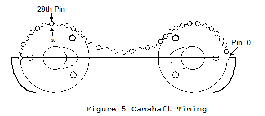
Install the exhaust camshaft first. The exhaust camshaft is the one with the gear for the tach drive. The camshaft goes in with the bolt heads on the sprocket facing to the right of the motor. There is an arrow on the rubber portion of the sprocket next to the bolt that is by itself. This arrow should point directly forward when the camshaft is bolted in place, reference Figure 5 Camshaft Timing.
Next, align the Intake camshaft. On the rubber portion of the intake sprocket is an arrow and the number 28. The chain roller that occupies this spot is twenty eight roller pins from the one with the arrow on the exhaust sprocket. Note that the arrow on the exhaust sprocket is number zero. Start counting to twenty eight on the next chain roller above the zero. The lobes of the camshafts should be as pictured when tightened in place. Keep some tension in the middle of the cam chain between the two sprockets to prevent rotation
Next, bolt the exhaust camshaft in place. Start with cam tower “1”. Verify there are two babbet cam bearings installed. Verify there are two dowel pins installed at opposite corners of the cam tower. The number 1 cam tower has thrust surfaces on it. That means that it keeps the camshaft from moving sideways in the head. Cam tower 1 goes on the left side of the motor, the number 1 should be upright when sitting on the bike. Verify that the thrust surfaces of the camshaft are between the thrust surfaces of the cam tower. Lubricate the four shouldered 6mm bolts with oil and install and tighten them down until they contact the top of the cam tower. The dowel pins should be started in the holes. Install cam tower “2”. Again, verify there are two babbet cam bearings and two dowel pins intalled. Place cam tower 2 on the right side of the camshaft and tighten the bolts until they contact the cam tower. Tighten the bolts a little at a time. Try to keep the camshaft at an even height in the head. Work your way around until there is no gap on either cam tower. The final torque should be 70 – 80 in lbs. Or, if you do not have an inch pound torque wrench, snug.
Next, bolt the intake camshaft in place. The procedure is the same as the exhaust camshaft. The cam towers are number 3 and 4.
Push the cam chain down between the two camshafts. Check the crankshaft postion for 1-4 T. Verify the camshaft timing is the same as Figure 5 Camshaft Timing.
 Finally install the center top cam chain idler assembly. It consists of the following:
(4) 6mm X 35mm (1.378”) bolts
(4) steel shouldered dowels
(2) upper rubber dampers
(2) lower rubber dampers (this part may separate into a rubber
damper and a steel plate, if so, it will still work, make
sure you have all of the parts)
(1) top cam chain idler
Lubricate the bolt threads before installation. Tighten the bolts a little at a time in a circular pattern until all the slack has been removed. The final torque should be 80 – 100 in lbs. Or, if you do not have an inch pound torque wrench, snug.
Reinstall the tach drive gear.
Lubricate all cam lobes and cam followers generously with 30 weight oil.